
In the Blackberry-keyboard-based project lineage story last week, I covered how a series of open-source projects turned into Beepy, a cool Linux PDA with a lively community. To me, it’s yet another demonstration of power that open-source holds, and more importantly, it shows how even a small pet project of yours could cause big moves in the hardware world, provided you publish it – just ask [JoeN], [WoodWorkeR] and [arturo182].
The journey didn’t end there. For all its benefits, Beepy had some flaws to take care of, some board-killing flaws, even. The 5 V boost regulator was never intended for 4.7 V input it gets when charger is connected, and would occasionally cook itself. A charging current resistor was undersized, leading people to either bodge resistors onto their Beepy boards, or have their battery charge for 30 hours until full. A power path diode was undersized, too, and has burned out on more than a few devices. Also, Beepy’s feature package left things to be desired.
Beepy never made it beyond v1. If I had to guess, partially because of BB Q20 keyboard sourcing troubles, but also definitely some sort of loss of interest. Which is a shame, as the plans v1.5 of the hardware were pretty exciting. In the meantime, other players decided to take up the mantle – here’s a tale of three projects.
Improved, Colorful, Closed
I like to talk about all sides of open-source hardware, good and bad. We’ll start with the bad here. Sometimes, you’ll publish a project under an open license that requires other people to share their work if it’s based on your project files. Then, someone takes your files, makes none to minimal changes, closes the sources, maybe even completely removes the attribution, and starts selling them. That’s the story of Colorberry.
 Left: OG Beepy, right: Colorberry; spot 10 differences. If one of them is “stripped of all attribution”, you get bonus points.
It was one of the first Beepy derivatives — seemingly fixing two of the three Beepy bugs, and adding support for a color display from JDI. Unfortunately, it also removed some important elements: namely the attribution to the Beepy on product or project pages – and closed-sourced the files.
Beepy’s PCB is licensed under a reciprocal (copyleft) license, which means that derivative product designers are supposed to share any changes they make. Without access to the source, it’s difficult to confirm that Colorberry really fixed the upstream Beepy bugs. It also makes it harder to diagnose and repair the hardware, and limits the chances the Colorberry would live on should its creator step away from the project.
Unfortunately, the problems don’t stop there. The code to drive the color screen is heavily based upon a driver produced by people in the Beepy community. Like the Beepy hardware, the license for the driver (GPL) requires that changes made to the code be made public. But when Alex, the Colorberry developer, was asked about publishing the code for this driver, he responded that it would happen “once the driver is ready.” A year later, the new story is apparently that he will release the sources once his personal stock of color screens runs out.
Because the driver is only published as (non-stripped) binaries on GitHub, it needs to be recompiled and republished by Alex with every Linux kernel update or distro that Colorberry could be used with. It’s also markedly harder to install (to the point people had to concoct multi-step install scripts), and I have it on good authority that the driver contains a bug that will actually reduce the lifetime of the display. But without the source for the driver, the community can’t fix it.
 I confirmed this later on, having looked at the binary files myself – indeed, even the typos from someone else’s open-source driver are still present in Colorberry driver code.
From what I’ve seen, the Beepy open-source design has been a crucial factor for its community to flourish and keep thriving even two years later. Colorberry’s puzzling closed-source decisions just don’t add up to the same value, and I gather that’s a big part of why the project didn’t gain more traction.
The Colorberry isn’t the only Beepy clone to keep the hardware source to itself. The PiBerry from CarbonComputers doesn’t fix the bugs from the original handheld, unfortunately, but it does bring a higher resolution color display to the party. It also doesn’t try to erase its lineage, with both the PCB silkscreen and the documentation referencing the fact that it’s based on the Beepy. Even still, the board design files aren’t included in the PiBerry repository.
What’s interesting in this case is that CarbonComputers later made a newer PiBerry version in same form-factor, aimed at assembly from more off-the-shelf components, and that version does have its KiCad files published. I’m willing to give the creators the benefit of the doubt here, and say that not including the source files for the previous versions of the hardware might simply be an omission on their part and not intentional.
These two weren’t the only projects coming to life because of Beepy’s success – at times, if you get someone inspired enough with a project of yours, they could end up building an entire lineup of gadgets. Such is the case of Hackberry Pi, a project coming from a hacker named Zitao.
The Hackberry Family
 Ever wanted the power of a Pi 5 in a portable package? That’s where you reach for the Hackberry Pi. The CM5 version is way sleeker than this one, I gotta say.
You might’ve seen the Hackberry Pi around – it’s a Beepy-like device with a 720×720 DPI screen derived from Adafruit’s Hyperpixel design and a Q20 keyboard. A number of parts in the first Pi Zero-based versions of the Hackberry Pi were visibly derived from the Beepy design. However, at least the later versions have been re-drawn from scratch in EasyEDA, with a number of diverging design paths, and Zitao has been prolific in building newer and generally better versions of the platform.
From a Pi Zero-based version with Nokia batteries, to Pi 5-based device powered by 18650s, the Hackberry has gone through quite a journey. Just a couple days ago from the time of this writing, the Compute Module-based version of the Hackberry Pi has become available, and it’s been selling like hotcakes.
Zitao’s hardware is inspiring in a few ways. For instance, the ways in which these devices avoid driver installation requirements, with keyboard connected over USB instead of I2C, powerbank chips with LED battery level display instead of the Beepy’s RP2040, and it goes even to the point of soldering a small Bluetooth receiver module onto the board to drive the onboard speakers from the Pi running the show. It’s a kludge, but at the same time, it’s hard to argue with things that work well in practice!
Hackberry Pi devices are also closed source, but at least schematics have been made available. This is good enough to spot most bugs, and those schematics have already been useful for people pointing out poor design decisions in the first versions. Of course, it’s still against the spirit of open-source and in particular the project that made Hackberry Pi possible in the first place – but at least it’s a step in the right direction.
Our Radically Open Beepy Clone
As you might have guessed, I don’t like closed-source devices. In particular I dislike devices that benefit from an open-source ecosystem and then burn the goodwill provided, as if to sterilize and salt the land that would otherwise serve other projects in the future.
 Two v1 Blepis units: one assembled with a Sharp display, another with a cheaper color SPI one.
Over the last half a year, I’ve had the privilege of working on the Blepis, a Beepy successor built by a hacker collective I’m a part of, called HackMods. We’ve designed, planned out, and assembled the first versions of these boards together, with the goal of having a fleet of Linux PDAs.
Made by hackers for hackers, it’s an experiment in just how far you can push the Beepy design, and we’re keeping things as open-source as we found them – arguably even more so! In particular, even our case design is in FreeCAD and open-source, with .FCstd files included.
First major improvement we made was in screen support. Sharp Memory screens can be expensive and are often out of stock for months, and JDI screens are even more expensive than that, often the only options are overpriced eBay listings. This is somewhat okay for a one-off, but it is very sub-optimal if you’re building a fleet of a dozen hacker PDAs for you and your friends.
That’s why we’ve added support for the commonly available 3.2″ 320×240 18-pin SPI color screens in addition to Sharp and JDI screens. We even have touchscreen controller support for the 18-pin panels that come with a touch layer, and support backlight on displays which have it. Of course, the known Beepy bugs are fixed as well. Our 5 V boost is operating within spec, and we have a switch-mode battery charger expected to give off barely any heat at all while providing a fair bit of charging current.
 The PCB, done mainly by [LinaLinn] and me, with others’ contributing to it in various ways. It would probably be easier to talk about what we didn’t add. Thankfully, for those things, we have an expansion connector!What else? Just for a start, we added an RTC, a vibromotor driver, and an onboard buzzer, not to mention things like QWIIC connectors for I2C and USB.
The Beepy didn’t have any onboard USB peripherals – you were expected to make use of the Pi Zero’s microUSB port. But we’ve added a whole USB ecosystem onto all the free space on the board – including a microSD reader, a slanted USB-C slot letting you connect a small USB-C 3.5 mm dongle soundcard for music playback (or other devices), and a USB hub chip to tie it all together. Apart from that, we support host mode on the bottom “charging” USB-C port, too – complete with 5 V power output.
Some of these features, like power output on the main USB-C port, are not supported by the firmware yet, But we’ve gotten pretty familiar with Beepy firmware while building v1, so, adding firmware support for those features is not expected to be that complicated.
Our expansion connector is also unparalleled when it comes to interfaces we expose. A single-row 23-pin header has 3.3 V, 5 V and VBAT power rails with over-current and backflow protection, plus I2C, SPI, UART, SDIO, PWM, and I2S, all ESD-protected.
We’ve already had a LoRa expansion module contributed by someone from the Beepy community, and one of our members has designed a DECT board. We plan on doing doing boards aimed at general-purpose hacking & BIOS chip flashing soon. If you ever wanted a PDA with a powerful expansion header for hardware hacking purposes, this is the design for you.
The Gift Of Giving Back
If you’re looking for a Linux PDA board, I hope you can appreciate the Blepis hardware design we bring to you, only possible because of a string of open-source projects before it. Our design files and driver/firmware sources are all on GitHub and GitLab, with a summary available on [Michael]’s BBKB ecosystem website.
Blepis is meant to work with JLCPCB PCBA, and we have a GitLab integration for exporting the project files – all the JLC part numbers are input into the schematics, so just upload the files and get a batch of motherboards delivered to your doorstep. To complete it, get a Pi Zero, a battery, a Blackberry Q20 keyboard, a display out of the list of supported ones, print the shell (v2-compatible shell coming soon), and off you go.
Seeing entirely new projects happen, each cooler and more advanced than the previous one, all because people kept publishing their code and PCB files, and then, getting to build a dream device for me and my friends thanks to someone else’s work – these kinds of experiences are what radicalized me in favour of being fervently pro-open-source. I see open-source philosophy live and thrive through dreams of hackers and barrels of viral licenses, through publishing despite imperfections, and building off each other’s dreams to turn the tide of tomorrow. I hope you get to experience it, too.
From Blog – Hackaday via this RSS feed

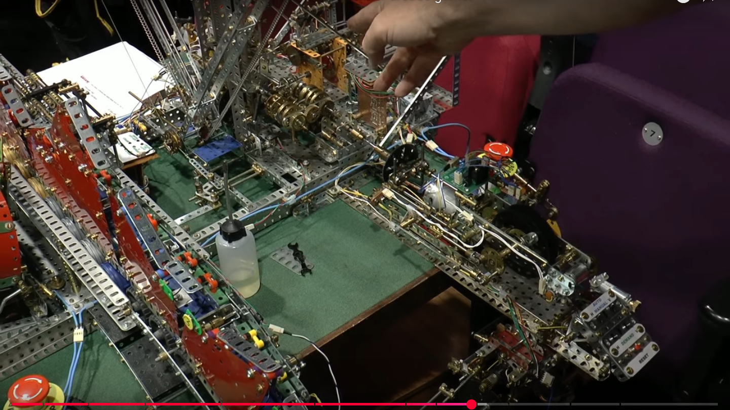 The brains of the operation: cams and gears, and ingenuity.


