
Historically, efforts to create original games and tools, port over open source emulators, and explore a game console’s hardware and software have been generally lumped together under the banner of “homebrew.” While not the intended outcome, it’s often the case that exploring a console in this manner unlocks methods to run pirated games. For example, if a bug is found in the system’s firmware that enables a clever developer to run “Hello World”, you can bet that the next thing somebody tries to write is a loader that exploits that same bug to play a ripped commercial game.
 But for those who are passionate about being able to develop software for their favorite game consoles, and the developers who create the libraries and toolchains that make that possible, the line between homebrew and piracy is a critical boundary. The general belief has always been that keeping piracy at arm’s length made it less likely that the homebrew community would draw the ire of the console manufacturers.
As such, homebrew libraries and tools are held to a particularly high standard. Homebrew can only thrive if developed transparently, and every effort must be taken to avoid tainting the code with proprietary information or code. Any deviation could be the justification a company like Nintendo or Sony needs to swoop in.
Unfortunately, there are fears that covenant has been broken in light of multiple allegations of impropriety against the developers of libogc, the C library used by nearly all homebrew software for the Wii and GameCube. From potential license violations to uncomfortable questions about the origins of the project, there’s mounting evidence that calls the viability of the library into question. Some of these allegations, if true, would effectively mean the distribution and use of the vast majority of community-developed software for both consoles is now illegal.
Homebrew Channel Blows the Whistle
For those unfamiliar, the Wii Homebrew Channel (HBC) is a front-end used to load homebrew games and programs on the Nintendo Wii, and is one of the very first things anyone who’s modded their console will install. It’s not an exaggeration to say that essentially anyone who’s run homebrew software on their Wii has done it through HBC.
But as of a few days ago, the GitHub repository for the project was archived, and lead developer Hector Martin added a long explanation to the top of its README that serves as an overview of the allegations being made against the team behind libogc.
 Somewhat surprisingly, Martin starts by admitting that he’s believed libogc contained ill-gotten code since at least 2008. He accuses the developers of decompiling commercial games to get access to the C code, as well as copying from leaked documentation from the official Nintendo software development kit (SDK).
For many, that would have been enough to stop using the library altogether. In his defense, Martin claims that he and the other developers of the HBC didn’t realize the full extent to which libogc copied code from other sources. Had they realized, Martin says they would have launched an effort to create a new low-level library for the Wii.
But as the popularity of the Homebrew Channel increased, Martin and his team felt they had no choice but to reluctantly accept the murky situation with libogc for the good of the Wii homebrew scene, and left the issue alone. That is, until new information came to light.
Inspiration Versus Copying
The story then fast-forwards to the present day, and new claims from others in the community that large chunks of libogc were actually copied from the Real-Time Executive for Multiprocessor Systems (RTEMS) project — a real-time operating system that was originally designed for military applications but that these days finds itself used in a wide-range of embedded systems. Martin links to a GitHub repository maintained by a user known as derek57 that supposedly reversed the obfuscation done by the libogc developers to try and hide the fact they had merged in code from RTEMS.
Now, it should be pointed out that RTEMS is actually an open source project. As you might expect from a codebase that dates back to 1993, these days it includes several licenses that were inherited from bits of code added over the years. But the primary and preferred license is BSD 2-Clause, which Hackaday readers may know is a permissive license that gives other projects the right to copy and reuse the code more or less however they chose. All it asks in return is attribution, that is, for the redistributed code to retain the copyright notice which credits the original authors.
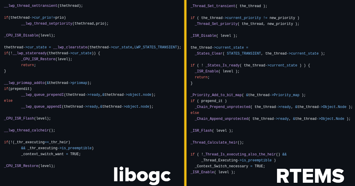
In other words, if the libogc developers did indeed copy code from RTEMS, all they had to do was properly credit the original authors. Instead, it’s alleged that they superficially refactored the code to make it appear different, presumably so they would not have to acknowledge where they sourced it from. Martin points to the following function as an example of RTEMS code being rewritten for libogc:
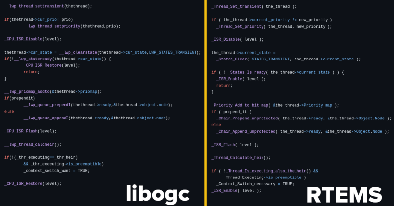
While this isolated function doesn’t necessarily represent the entirety of the story, it does seem hard to believe that the libogc implementation could be so similar to the RTEMS version by mere happenstance. Even if the code was not literally copy and pasted from RTEMS, it’s undeniable that it was used as direct inspiration.
libogc Developers Respond
At the time of this writing, there doesn’t appear to be an official response to the allegations raised by Martin and others in the community. But individual developers involved with libogc have attempted to explain their side of the story through social media, comments on GitHub issues, and personal blog posts.
The most detailed comes from Alberto Mardegan, a relatively new contributor to libogc. While the code in question was added before his time with the project, he directly addresses the claim that functions were lifted from RTEMS in a blog post from April 28th. While he defends the libogc developers against the accusations of outright code theft, his conclusions are not exactly a ringing endorsement for how the situation was handled:
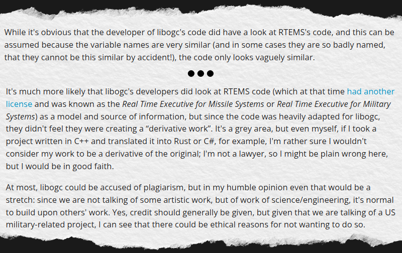
In short, Mardegan admits that some of the code is so similar that it must have been at least inspired by reading the relevant functions from RTEMS, but that he believes this falls short of outright copyright infringement. As to why the libogc developers didn’t simply credit the RTEMS developers anyway, he theorizes that they may have wanted to avoid any association with a project originally developed for military use.
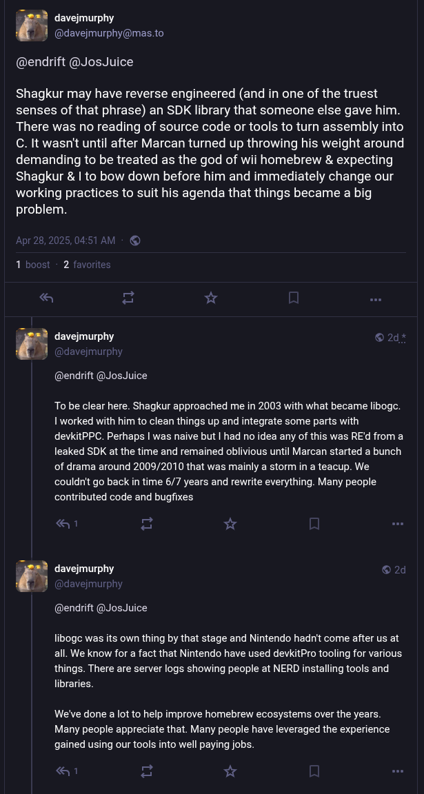
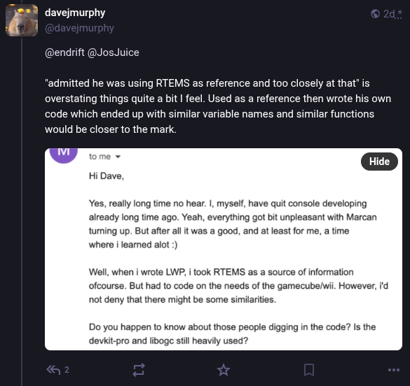
As for claims that libogc was based on stolen Nintendo code, the libogc developers seem to consider it irrelevant at this point. When presented with evidence that the library was built on proprietary code, Dave [WinterMute] Murphy, who maintains the devkitPro project that libogc is a component of, responded that “The official stance of the project is that we have no interest in litigating something that occurred 21 years ago”.
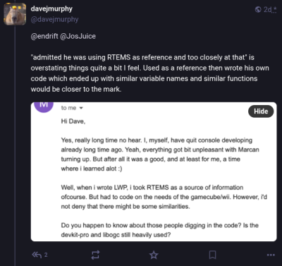
In posts to Mastodon, Murphy acknowledges that some of the code may have been produced by reverse engineering parts of the official Nintendo SDK, but then goes on to say that “There was no reading of source code or tools to turn assembly into C”.
From his comments, it’s clear that Murphy believes that the benefit of having libogc available to the community outweighs concerns over its origins. Further, he feels that enough time has passed since its introduction that the issue is now moot. In comparison, when other developers in the homebrew and emulator community have found themselves in similar situations, they’ve gone to great lengths to avoid tainting their projects with leaked materials.
Doing the Right Thing?
The Wii Homebrew Channel itself had not seen any significant updates in several years, so Martin archiving the project was somewhat performative to begin with. This would seem to track with his reputation — in addition to clashes with the libogc developers, Martin has also recently left Asahi Linux after a multi-bag-of-popcorn spat within the kernel development community that ended with Linus Torvalds declaring that “the problem is you”.
But that doesn’t mean there isn’t merit to some of his claims. At least part of the debate could be settled by simply acknowledging that RTEMS was an inspiration for libogc in the library’s code or documentation. The fact that the developers seem reluctant to make this concession in light of the evidence is troubling. If not an outright license violation, it’s at least a clear disregard for the courtesy and norms of the open source community.
As for how the leaked Nintendo SDK factors in, there probably isn’t enough evidence one way or another to ever determine what really happened. Martin says code was copied verbatim, the libogc team says it was reverse engineered.
The key takeaway here is that both parties agree that the leaked information existed, and that it played some part in the origins of the library. The debate therefore isn’t so much about if the leaked information was used, but how it was used. For some developers, that alone would be enough to pass on libogc and look for an alternative.
Of course, in the end, that’s the core of the problem. There is no alternative, and nearly 20 years after the Wii was released, there’s little chance of another group having the time or energy to create a new low-level C library for the system. Especially without good reason.
The reality is that whatever interaction there was with the Nintendo SDK happened decades ago, and if anyone was terribly concerned about it there would have been repercussions by now. By extension, it seems unlikely that any projects that rely on libogc will draw the attention of Nintendo’s legal department at this point.
In short, life will go on for those still creating and using homebrew on the Wii. But for those who develop and maintain open source code, consider this to be a cautionary tale — even if we can’t be completely sure of what’s fact or fiction in this case.
From Blog – Hackaday via this RSS feed


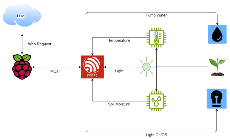
![The future of healthy indoor plants, courtesy of AI. (Credit: [Liam])](https://hackaday.com/wp-content/uploads/2025/04/plantmom_test_setup_with_plant.jpg)


