1
1

cross-posted from: https://lemmy.ml/post/28250870

Hello everyone !

I'm seeding/cross-post this in 3 communities because I think I will get better answers in each respective one (Hardware, coding, electronics).

As the title say I'm want to learn to build from the ground up those cheap solar led/optic fiber lightning, here some images to get what I mean:

They come in bundles but after awhile they just die out without repair ability which kinda sucks and because they are cheap my mum keeps buying them... So, I would like to build ones I'm able to repair and customize :). However I have absolutely NO idea where to begin and what exactly I'm searching for... I'm lacking the skills and knowledge on the 3 fronts !

  • What hardware I'm looking for ?
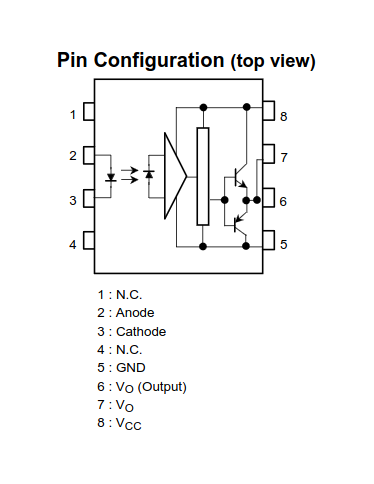
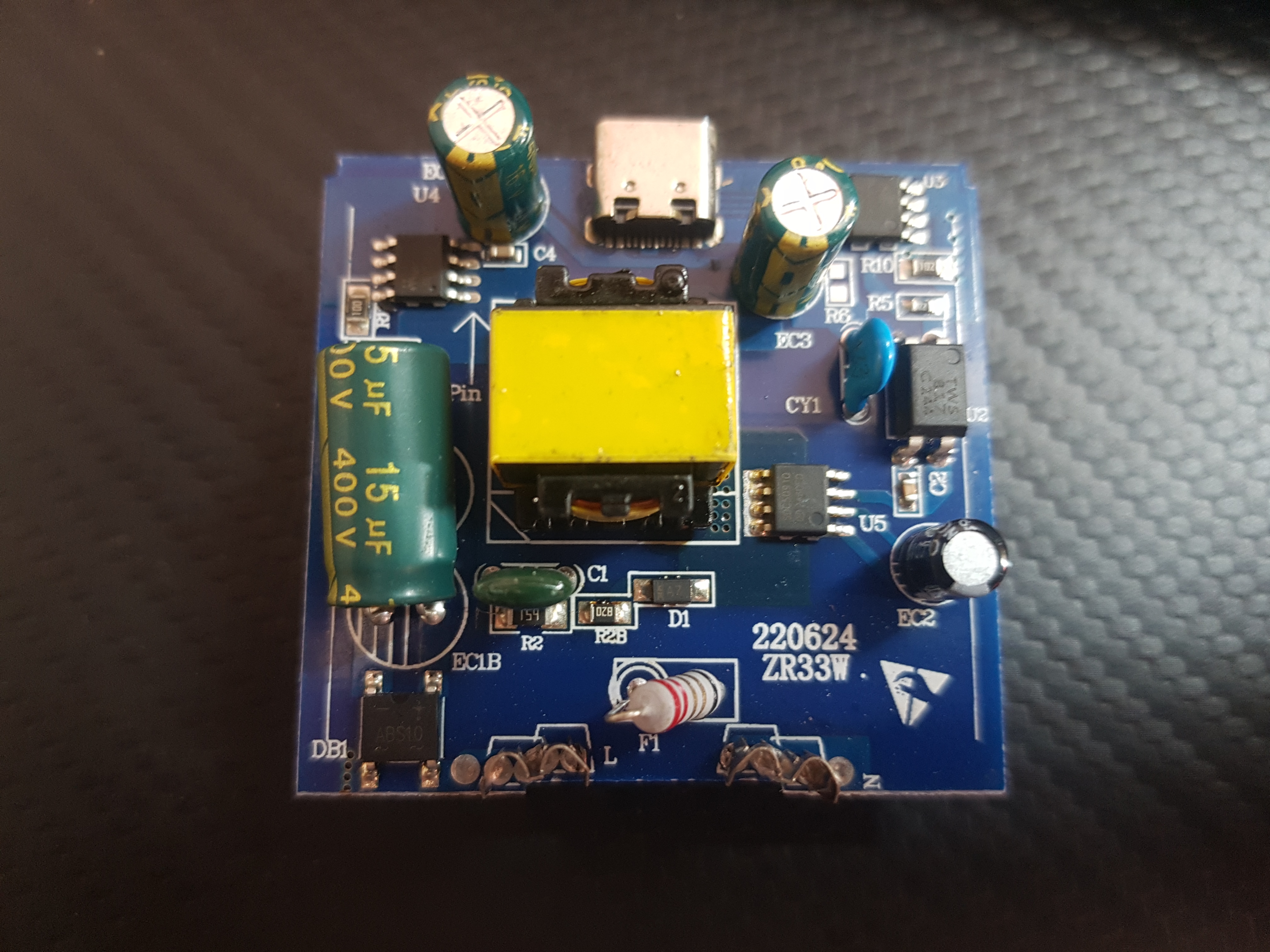
  • What kind of electronics ?
  • What programming language to glue everything together?
  • .... ?

I'm not afraid to get my hands dirty and learn how to micro-solder, learn some coding skills to get everything neatly glued together software wise, learn the necessary hardware or other important and necessary stuff to achieve this goal ! I'm looking for every good and reliable advice to get me started !

One thing though, If i have to learn some hardware/low level coding skills I would prefer a language that would be useful for other stuff in the long run.

Thank you in advance and I'm already sorry if I'm very slow to respond, I'm not native and the flood amount of information I will probably get, will surpass my ability to respond to everyone right away.

Also every other directions are welcome, like:

  • how to repair the old ones? Do I need to flash their proprietary software/hardware?

Thank you !

2
1

I replaced this battery last fall, but it has drained over the winter. The auto-mower dock wont charge it. Is there any feasible way to charge it safely? Or is it dead at that voltage? It’s a Bosch Indego 400. Thanks in advance.

3
1
submitted 3 weeks ago* (last edited 3 weeks ago) by user@lemmy.one to c/askelectronics@discuss.tchncs.de

Hi, Any1 have experience with this usb to TTL 6 pin converters? I just want to know if I have a dodgy one that I bought from Ali or normal behaviour.

Doesnt seem right. I have it plugged to a powerbank, following voltages read from pinout, without any jumper link.

5v = 5.3 Vcc = 3.9v 3.3 = 3.2v Tx RX = 3.9v

If I use jumper link from 5v to VCC, then tx RX = 5.3v, if I jumper link VCC and 3.3, RX and tx = 3.9v.

Thanks for reading

Photo of product http://0x0.st/81fc.jpg

4
1

I'm making a driver for a small 15V, hall sensored, 9-slot BLDC motor I got off of AliExpress. It has u,v,w inputs. Three hall outputs and Vcc, Gnd for them. No datasheet :)

I understand the working principle: I'll have to use the hall sensors to figure out the location of the rotor, then power the appropriate windings.

Trouble is, I don't know how the windings for the three phases are arranged within the motor. So I don't know which pin to give power to, because I don't know which windings within the motor will then be powered.

How can I figure out where the windings are for each phase?

I'm guessing I've got to manually spin the motor and do some detective work with back-emf measurements and hall sensor outputs to figure this out?

5
1
submitted 1 month ago* (last edited 1 month ago) by foremanguy92_@lemmy.ml to c/askelectronics@discuss.tchncs.de

I've an UPS but it's not working fine. Disassembled it a bit and tested components that I could without unsoldering, everything seems good. Then the problem is :

  • Normally I should be able to connect the batteries and the UPS would just be in "sleep" mode, the screen would be fully light up but the UPS should be off

  • The problem here is that firstly when I plug batteries the fan turns on, it should not and only turned on when on batteries but when the UPS is on

  • The second problem is that the screen doesn't work as intended. This is a screen that has prewritten zone that just have to be lighted up (don't know the name of this kind of screens, the type like in digital clock), here only the backlight is lighted up (normally all the possible drawing are lighted up too), but quickly it begins to drop in lightness to turn black at the end (the fan continues running)

Check the batteries they are 2 x 12V at 12.6V here

Thanks for your answer

EDIT : on the photo the two blue and brown cable at right are the power plant electricity going to the UPS

6
1

So I'm not sure what the right community for this is but I'm hoping yall can help. I'm a refrigeration service tech and recently I was tasked with replacing a sensor in a room used to store ethanol drums. Due to the nature of the room every device in it had to be rated explosion proof and I couldn't use any tools that could pose any risk of ignition (no heat gun, basically nothing with an electric motor, and definitely no open flames) while working in there. Normally when I splice wires I use heatshrink to cover the splice simply because it looks far more professional than electrical tape and it holds up better over time. However in this case I could not figure out any way of shrinking said heatshrink without posing a potential ignition hazard so I was stuck just wrapping the splice in tape. We do a lot of work for this company so I'm hoping to find a better solution for the next time I am in a similar situation.

So do any of you know any way to shrink heatshrink without posing an ignition hazard or am I stuck just using tape in those situations?

7
1

Hi all! I'm a firmware developer with little knowledge in analog electronics.. I deal with firmware for IOT projects all the time.

I had to make a breakout board with an off the shelf RF module with self contained PCB antenna. Now I'm intrigued in the hardware side. I'm inclined to design them from scratch myself. (Obviously ignoring the EMI and FCC certifications for the time being).

What concepts should I be familiar with to achieve this? Starting on I figured to brush up on circuit theory and signals. Where do I go from here? What materials would you recommend? Hopefully I don't need to get into hardcore RF theory to design these PCBs (I know kicad already has these premade antenna blocks).

Thank you.

8
1

I'd like to build a small light that i can use to cast a shadow to a wall.

It needs a single led that's really small and bright and that can be recharged. Also I want to put it in a special casing.

However I don't really know how to build one myself. So I had the I bright idea to take apart a flashlight that is rechargeable, but I'm not sure which one can be dismantled.

Do you have any idea what flashlight I could use or what parts I would need?

9
1

Why do you like it? Why did you choose it? Would you recommend it?

10
1
submitted 2 months ago* (last edited 2 months ago) by atempuser23@lemmy.world to c/askelectronics@discuss.tchncs.de

I'm looking for a recommendation on a high quality 2 or 3 meter USB-C /Thunderbolt cable used for data transfer and charging.

After yet another replacement Anker cable usb-c cable I’d really like to get cables that can last a few hundred cycles and I need a recommendation.

Are there any companies that make higher durability cables?

--Edit-- So far recommendations I have gotten are

  • Samsung
  • LCom
  • cable matters
  • Braided jackets
  • Power delivery of 25w or greater
  • Use magnetic disconnects
11
1
submitted 2 months ago* (last edited 2 months ago) by foremanguy92_@lemmy.ml to c/askelectronics@discuss.tchncs.de

I have an UPS with two 12v 7ah lead batteries. If I want to change the batteries I would typically go with lead batteries but here's my question, can I use some portable mobile power banks to use it?

Because I have a 20000mah "INUI" lithium power bank that is rated for 12v at 1.5A, is it a good practice to buy several of these (since they are about 20 bucks) disassemble them and use them as ups batteries?

EDIT : clarifications

12
1

So, i'm thinking of a story and i need some tech info.

How risky is to de-solder an usb plug if the flash-drive contains important files? It would be relatively safe for someone capable, or the heat is way too risky for the chip/content?

Also there's any (MacGyver like) way to quickly access the file or reconnect the plug without a solder while only having access to office supplies?

13
1

I have a pet project I've been working on to modernize an electric organ console, and one of the final things needed are toggle switches. On a modern organ these are able to be manually toggled, or they can be flipped up/down programmatically using electromagnets (video). The ones purpose built for this are obscenely expensive but I can't find anything even remotely similar. Am I crazy for thinking this kind of switch are used in more things than just organs?

14
1
submitted 2 months ago* (last edited 2 months ago) by MacAnus@sh.itjust.works to c/askelectronics@discuss.tchncs.de

Hi all,

Do you have some recommendations for a soldering station that would meet my needs?

I've been into hobby electronics for a few years, doing mostly analog audio projects but recently got into repairing and repurposing broken electronics (Bluetooth earbuds, speakers, USB cables and such).

I've been using a cheap Parkside(LIDL)-rebranded "generic Chinese product" (I came across the exact same model on AliExpress, in different colors); which has served me well until now but has a few flaws that I can't be bothered with anymore. Mainly: -it takes ages to get hot. -the cable going from the station to the iron is super thick and stiff, which is annoying as hell...

I would like it to be the least expensive possible, while being good enough I'd be happy with it for the foreseeable future.

I have been looking at these:

Old tech, cheap tips (<1€)

Newer tech, "expensive" tips (8-10€)

And wondering how these "newer" types of iron compare to stations, what are the main drawbacks?

Thanks a lot in advance for any input, Please be gentle if you think I'm an idiot :)

Edit: changed the "Smolderin" in title to "soldering"

15
1

I've got a used riello ups recently and it was not working since the beginning. The UPS was switching to batteries most of the time, but sometimes it just don't switch to batteries and makes a continuous beep (riello manual tells that it's a UPS fault anything except an overload).

I left it 2 weeks without using it. But know it won't start at all. Don't have the materials to test components for now but what are your ideas? (Even when plugged in the wall it wouldn't start)

Maybe batteries or faulty ups

Thx

16
1
safe? (lemmy.ca)

17
1

I haven't really been able to find much on this. I recognize the totem-pole and what that's for. Would love help understanding:

  • What's the triangle?
  • What's the rectangle immediately after?
  • Why are there two outputs instead of one? A lecture I watched claimed this is common.
18
1

I've got a few projects on the list which will be battery powered. I'm thinking of using 18650s just because of how ubiquitous they are, but I know there's other options out there. Are they worth it?

  • E-ink calendar
  • Solder fume extractor
  • Lora station
  • Portable "trail camera"
  • Home assistant remote controls Etc etc etc
19
1

So, I had some issues with installing the GPU in the case, and the GPU bottom (those metals things at the bottom) ended up scratching part of the motherboard. From what I can tell, there's a bunch of similar components all the way up, so I'd think there's redundancy, so I guess it's not that important. Here is a picture (I was told some people couldn't open postimg, both links have same image):

https://i.postimg.cc/7LBwkr3h/62e626.jpg

https://files.catbox.moe/62e626.jpg

PC boots fine into bios, fans work, stuff are recognized, mouse and keyboard also works, but I haven't really done much beyond that.

Motherboard is: MSI B650 Gaming Plus Wifi

It's located here, and on them, it is written K72 then vertically smaller K2 (the 2 has an underline), as you can see in the above image too:

https://i.postimg.cc/XJNcnppT/modelblock-gaming-pd.png

https://files.catbox.moe/7otcn6.png

I was told to ask here, and the best guess from what I've been told is that this is this:

Paralleling power metal-oxide semiconductor field-effect transistors (MOSFETs) is a common wayto reduce conduction losses and spread power dissipation over multiple devices to limit the maximum junction temperature.

Which could mean that the others could pick up the slack.

Should I get a new motherboard?

20
1
submitted 3 months ago* (last edited 3 months ago) by foremanguy92_@lemmy.ml to c/askelectronics@discuss.tchncs.de

cross-posted from: https://lemmy.ml/post/24328274

Hey I need your help.

Recently I bought a Riello NPW 2000 that output a "pseudo-sinusoidal" wave when running on battery the fact is that I read on the web that modern servers could have problems with it.
Mostly right, as I found that my server (poweredge t430) is not running good with it. When unplugging the power to test the UPS sometimes it make the server just power off and reboot (as said in the bios, turn on when power goes on again) or it put the ups in safety mode (continuous beep).
Tried disabling the PFC in IDRAC settings, as far I haven't noticed power off issues but only safety mode issues with the UPS... (So in fact the server power off, but will never go on battery)

In both cases the server is running fine on battery the issues are just happening when switching.

If anyone has an idea.. Thank you

After research I found that the server never turns off when disabling PFC but will eventually make the UPS goes into fault, I fought it was the fault of the PC that was putting the UPS in protection mode, but it was not the case as I tried to power a TV and it did the same thing.... So I'm good to buy another one...

EDIT : some clarifications & partly resolving the issues

21
1

It's not available anymore and even if it was, I don't really want to buy one from him. And I need about 15 anyway for the youth group activity. It's far more cost effective to order direct from pcb fab shop.

22
1

I’m working on driving a very finicky lcd. I have it working now with an FPGA dev kit. I had to use an FPGA because some of the timing requirements are in the tens of nanoseconds.

At the end of the day, I wrote a block for a one shot/continuous clock with a programmable duty cycle and initial delay. This block was repeated six times for the various clocks with their specific values.

Moving to the final product, this feels like overkill. In the past, I’ve managed to make this kind of thing work with a Rube Goldberg collection of on-board timer/counters on the microcontroller.

I’d like to avoid that mess this time around. If I can generate the clocks externally, I can have the host MCU send the data quickly using DMA.

An FPGA works great, but they’re expensive and there’s the issue of licensing for FPGA and and CPLD software.

I’ve seen this problem solved with a lookup table, but there aren’t a lot of cheap/small rom/ram options for what I’m trying to do.

Basically, what I’m asking is is there a component that can be easily programmed to generate a number of clocks, doesn’t need any costly software licensing, and comes in a very small package? (Like wlcsp)

23
1
submitted 4 months ago* (last edited 4 months ago) by ColdWater@lemmy.ca to c/askelectronics@discuss.tchncs.de

Found metal weight inside

24
1

I wanted to learn more about electronics, and I found this https://www.open.edu/openlearn/science-maths-technology/an-introduction-electronics/content-section-0 to start from so I can have a grasp on theories first, and I want to try learning microcontrollers afterwards but I can't afford to buy any IRL atm, are there any softwares to simulate them to assist on learning without having the physical hardware? I'd be happy if anyone could give me any tips toward that, thank you if you read this far

25
1
submitted 5 months ago* (last edited 5 months ago) by yokonzo@lemmy.world to c/askelectronics@discuss.tchncs.de

So I accidentally put an open water bottle in my bag while my tablet was in there, LCD was unfortunately flooded, but I ordered a replacement screen and it arrived today. Though opening up the tablet I found water droplets throughout, so I removed every part meticulously to put in rice or something and noted any current corrosion I had to remove with a q tip.

My question is this. As soon as I opened it up I noticed the water very quickly evaporating. I actually can't see any more now. Anyone who does mobile device repairs, what do you think? Could I skip the deep-dry? I looked at all the components and none of them have any parts that could have trapped water that I missed and I don't really look forward to cleaning the entire thing of starch ( though I do just have silica beads but let's stay on topic)

Am I right to feel confident about the dryness of the components? Let me know!

view more: next ›

Ask Electronics

3606 readers
42 users here now

For questions about component-level electronic circuits, tools and equipment.

Rules

1: Be nice.

2: Be on-topic (eg: Electronic, not electrical).

3: No commercial stuff, buying, selling or valuations.

4: Be safe.


founded 2 years ago
MODERATORS