Title basically.
One of my windows computers, which happens to be the one I happen to do the most CAD work on, can't upgrade to windows 11 due to having an Ivy Bridge era Xenon (it's an E5-1680 v2 for the curious, older used workstations are fantastic bang for the buck computers).
Switching to Linux on this computer has been in the cards for a while, but I hadn't been in a hurry to do it. Looks like my hand might be getting forced...

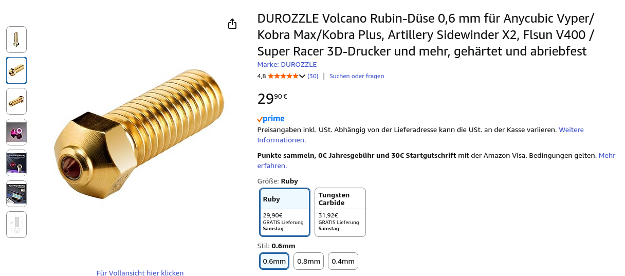
I'm thinkin about getting one of those ruby nozzles for my printers to basically be able to print anything without ever having to worry about a degrading nozzle. I've seen quite a few videos about it, but I still don't know two things:
- Given the surrounding material is brass and only the tip being out of ruby, doesn't the filament path where the molten filament gets pushed through still wear out over time (heavily so with CF or GF filament)?
And also
- How good are the cheaper ones, specifically the "DUROZZLE" one (since that's the one I could find that's 0.6mm and cheap)?
Hey there!
I want to design a 3d printing part for the dashboard of my golf 6, more precisely the top middle part right  .
.
I am somewhat experienced with designing parts in fusion 360 for daily usage, but I don't really know how to design this part.
I did try getting a fit for the front arc and an arc from the middle front to the middle back, then did construct a plane from both arcs and did round the result on both back edges. But I noticed when trying the fit, that the dashboard top is not really symmetric, but has an additional bump to the left.

Do you have any tips/guidance/ideas on how to get a better fit? I did think about scanning it 3d with some lidar device, but I don't have an iPhone and wouldn't know where else to get a device.
I do not know anything about 3D printing, let me know if another place might be more appropriate for this post.
My friend about three months ago was in a catastrophic motorcycle accident. He was hit by a texting F150 truck driver. He lost his leg, an eye and has had pretty much full body reconstruction, including jaw and face. He was wondering if he could 3D scan in the helmet he was wearing with all the first responders/doctors (who helped save him that night) signatures then give each one a copy to thank them. He is in Ontario/Brampton area. He can pay for it.
Picture is not of actual helmet. Being sent down from up north right now.


I have had no problems with my BambuLabs A1 (with AMS lite) for the most part and generally love it. But for some reason this last, simple 1 color, one object print started doing something weird. Every 20-30 cm of line printed it goes and purges. (See picture, where it had only printed a short line and then went to purge. See all those white poops? That's from a previous attempt where it stopped repeatedly to purge, similarly.) It does this repeatedly. Although I'm not an expert in 3D Printing I can't think of a reason a printer would be doing this? (The print seems to come out fine if I let it do it's thing, it just wastes a LOT of material and takes much longer than it should.)
It's PLA, BTW.


I'm now into my 3rd day with this printer, and while it's been pretty smooth sailing with PETG so far, I have noticed some consistent layer gore on the first layer. It is consistent across prints with large flat surfaces, and always in the same spots.
However, what made me curious is the fact that it seemed to be at perfect 45 degree angle and at regular intervals, as if it's some remnant of the first layer of another print.
These pectures were taken during the first print after cleaning the print sheet with warm water and dish soap. (I'm getting isopropyl alcohol next week).
Any tips and/or theories? The rest of the print comes out just fine, although I'm still tweaking the extrusion modifier.
.
.
.
PS: I'll gather additional data over time based on the tips and theories posted in here. I'll update the thread in a few days once I have some results (or lack thereof) to report.
UPDATE: For starters, slicer templates are at play. I didn't notice that I had reverted to default when loading a project.
Beyond that, I've started playing with extrusion multiplier as per recommendations in here, and it's getting better. I'm still trying to dial this in perfectly so that I get the other layers nice and full without nozzle accumulating any gunk. Once satisfied I'll play around with settings for first layer.
I guess the updated theory is that the print head movements of the first layer happens to cause washboarding in those positions even if I rotate the print. I would suspect a large surface print would instead of two would result in a single washboard patch.
Hey everyone,
I am currently recalibrating my printer after.not using it for a while. When doing a flow test I noticed these blobs forming in the middle of the circles.
AFAIK these are often caused by moistures in the filament. I already dried the filament at 50°C for a couple hours in the oven and the problem persists. So I guess I should simply get rid of the filament and open a new pack?
What's your assessment?

3DPrinting
3DPrinting is a place where makers of all skill levels and walks of life can learn about and discuss 3D printing and development of 3D printed parts and devices.
The r/functionalprint community is now located at: or !functionalprint@fedia.io
There are CAD communities available at: !cad@lemmy.world or !freecad@lemmy.ml
Rules
-
No bigotry - including racism, sexism, ableism, homophobia, transphobia, or xenophobia. Code of Conduct.
-
Be respectful, especially when disagreeing. Everyone should feel welcome here.
-
No porn (NSFW prints are acceptable but must be marked NSFW)
-
No Ads / Spamming / Guerrilla Marketing
-
Do not create links to reddit
-
If you see an issue please flag it
-
No guns
-
No injury gore posts
If you need an easy way to host pictures, https://catbox.moe may be an option. Be ethical about what you post and donate if you are able or use this a lot. It is just an individual hosting content, not a company. The image embedding syntax for Lemmy is 
Moderation policy: Light, mostly invisible